TDMA and Collocation Synchronization
Introduction
This article was written to describe Mimosa’s TDMA protocol selection, explain the importance of GPS and timing accuracy, review what controls are available for tuning performance, and to recommend best practices for collocating radios in mixed RF environments and in various network configurations.
Mimosa's Selection of TDMA
Time Division Multiple Access (TDMA) is a deterministic protocol where each device is assigned a time slot during which it is allowed to transmit. This allows for collocated radios to utilize the same channels and avoid Tx/Rx collisions and interference.
Mimosa’s approach, for maintaining high link reliability in 5 GHz-dense environments, is to load balance across two independent channels using TDMA (Figure 1). If one of the two channels experiences interference, the other channel is used to both transmit and receive all of the data.

Figure 1 – Mimosa TDMA link with two separate channels (blue and green)
Frequency-Division Duplex (FDD) is another protocol that also uses two channels. The first channel is used to send and the second channel to receive (Figure 2). If interference is experienced on either channel, the entire transmission is interrupted, and must be repeated. The reason for this is because both channels must remain free from interference for successful data transfer.

Figure 2 – Non-Mimosa FDD link with two separate channels
Because of its superior efficiency and enhanced resiliency compared with FDD, TDMA was selected for Mimosa’s backhaul products.
Importance of GPS and Clock Accuracy
A highly accurate and precise clock is needed for time-based protocols like TDMA to work reliably, especially across back-to-back links. This is because radios at the same site must synchronize their communication to avoid interfering with one another.
While there are several ways to synchronize radios, including out of band wireless or wired interfaces that tie to a single GPS receiver, the most flexible approach is to build an internal GPS receiver into each radio.
Mimosa’s engineers designed the B5 and B5c backhaul products with an integrated GPS receiver that receives signals from 24 GPS and 24 GLONASS satellites, an industry first. Having access to 48 potential satellites, twice as many as a pure GPS receiver, increases clock accuracy especially in areas where the view of the sky is limited.
GPS timing alone is insufficient, however, because of clock drift within each device. To ensure reliable time synchronization, the B5/B5c include a GPS-Disciplined Oscillator (GPS-DO) with 3 ppb (parts per billion), or 40 ns accuracy.
The GPS+GLONASS timing source and onboard GPS-DO enable synchronization between radios without requiring any form of communication between them. It is also possible to synchronize with other Mimosa radios on the same tower that are not under your control. The radio’s site-survey feature shows the TDMA configuration of other access points so the same configuration options can be selected for forward compatibility.
Once radios are synchronized, they can share the same frequencies at the same site. This is because both radios are either transmitting or receiving at the same time. Synchronization ensures that Radio 1 will not transmit while Radio 2 is receiving. Otherwise, Radio 2 would detect the signal from Radio 1 as noise.
TDMA Setup and Performance Tuning
The Media Access Control (MAC) layer, within Layer 2 of the seven-layer OSI model, provides channel control mechanisms for servicing multiple requests to use the physical layer (or PHY, Layer 1).
Some of these controls are available within the B5/B5c embedded user interface (Figure 3) and allow the user to fine-tune TDMA performance.
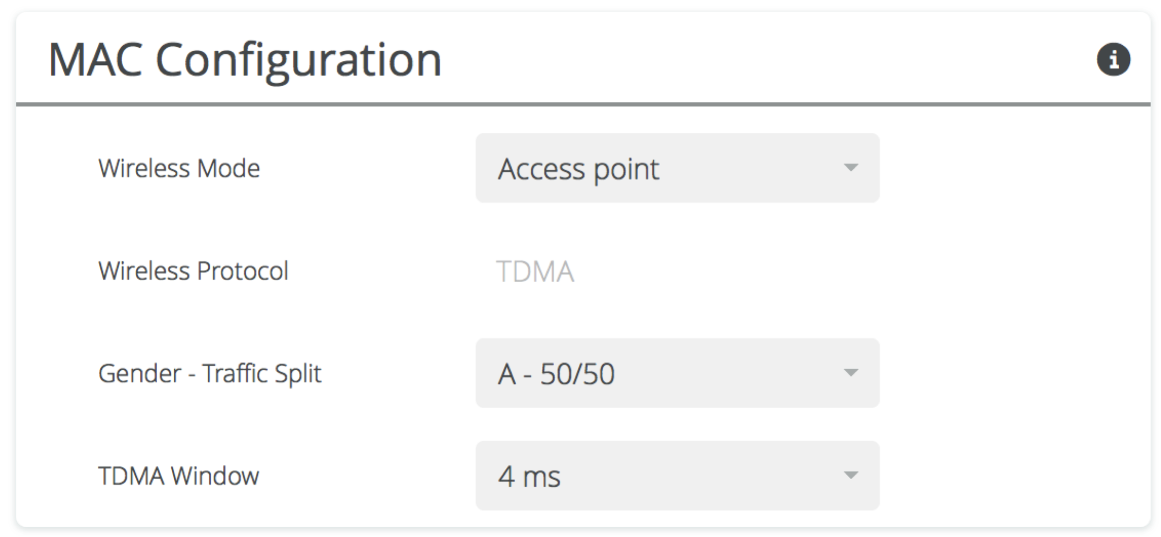
Figure 3 – MAC Configuration Controls
Wireless Mode
When creating a single hop point-to-point (PTP) link between two devices, one device is set as an Access Point (AP) and the other as a Station (STA) (Figure 4).

Figure 4 – Example PTP Link (Single Hop)
Note that once the channel(s), power, and TDMA settings are set on the Access Point, they are communicated to the Station automatically via 802.11 beacons.
Gender and Traffic Split
An important concept within the Mimosa TDMA protocol is that each radio in a link is assigned a gender: A or B. The Station’s gender is set automatically to the opposite of the Access Point. All devices with gender A will transmit at the same time, while those devices with gender B are receiving and vice versa. The gender should be set to the same value on all radios at the same site. For example, suppose you want to connect two sites with a relay in between. In Figure 5 below, note how Radio 2 and Radio 3 are assigned the same gender “B” since they are located at the same site.

Figure 5 – Example PTP Link (Multi-hop)
Both the gender and traffic split selection are combined within one control on the GUI. Therefore, you must also decide the TDMA Traffic Balance, which determines the percentage of time allocated for each side to transmit. There are two fixed options: 50/50 or 75/25 (Figures 6 and 7). Note that the slash notation in the GUI follows the convention (local/remote).

Figure 6 - 50/50 Traffic Split

Figure 7 - 75/25 Traffic Split
A third option called, “Auto” dynamically changes the duty cycle (ratio of Transmit to Receive) based on utilization of transmit slots by both the Access Point and Station. This option was designed to improve throughput efficiency and thus maximize the aggregate throughput over a single link. It is capable of changing the traffic split between Gender A and B to 25/75.
TDMA Traffic Split Options
50/50 Traffic Split
Choose 50/50 for multi-hop links, for ring topologies, or if you expect that downloads and uploads will be balanced, which may be appropriate for many business users. Figure 8 below shows a ring topology where a balanced traffic split is desired since traffic could move in any direction.

OSPF - Open Shortest Path First
BGP - Border Gateway Protocol
Figure 8 – Ring Topology (50/50 Traffic Split)
Building on the relay example from Figure 5, we’ll set a 50/50 traffic split (Figure 9). Multi-hop links cannot take advantage of uneven traffic splits because the relay transmissions are synchronized.

Figure 9 – Example PTP Link (Multi-hop) with 50/50 Traffic Split
72/25 Traffic Split
Choose 75/25 for single hop links (Figure 10) or star networks (Figure 11) if you expect that users will be downloading the majority of the time. These settings are useful for serving bandwidth-hungry, one-way applications such as video streaming services. Note that only radios with gender A may be set to 75% with the fixed 75/25 traffic split option, therefore when planning your network, the gender A radios should be placed closer to your bandwidth source (i.e. datacenter), with the gender B radios closer to the customer.

Figure 10 – Example PTP Link (Single Hop) with 75/25 Traffic Split

Figure 11 – Star Network with 75/25 Traffic Split
Auto Traffic Split
If the Auto option is chosen, the traffic split shifts dynamically among 75/25, 50/50, and 25/75 based on the transmit window utilization by each side of the link. Like the 75/25 option, the Auto option only benefits a single PTP link.
TDMA Window
The TDMA window describes the amount of time allocated for each radio to transmit. Adjust this value to optimize for latency or efficiency. Choose eight milliseconds to maximize raw throughput, two milliseconds to minimize latency, or four milliseconds to balance between the two.

Table 1 – TDMA Window Options
Each step in TDMA window size down from eight milliseconds (the reference value) incurs an approximate 10% throughput performance impact. This is due to the fact that smaller TDMA windows require more management overhead as a percentage of total data transferred.
There are some distance limitations to these options because propagation delay between a transmitter and receiver over a long distance may prevent data from arriving at the receiver before its transmit window. Free Space Path Loss (FSPL) limits distance with the 8 ms option.
Operators should also take into account the number of hops when setting TDMA window size to ensure that total latency meets requirements. For example, 5 hops and a 2 ms TDMA window size would result in 25 ms average round trip latency (5 hops * 2 ms * 2.5 = 25 ms).
All links in a multi-hop network, and all radios on the same tower for that matter, should be configured with the same TDMA window to avoid interference.
Recommendations for Collocation
When installing more than one radio at a site, you will want to ensure adequate physical separation and pay special attention to antenna direction. This is especially true for non-synchronized radios. This section will cover collocation with Mimosa and Non-Mimosa radios.
Mimosa Radios
One frequently asked question is, “How many GPS-synchronized Mimosa radios can be installed on the same tower”? The answer depends on several factors including the angular separation between antennas and differences in Rx signal strength. A better question might be, “What is the expected MCS index for two antennas at a given angle and with a difference in power input”?
To further explain, every antenna has a characteristic gain pattern within which signals are amplified in both directions (i.e. when sent from the local transmitter, and when received from the remote transmitter). By design, the main lobe of the antenna pattern has higher gain than the side and rear lobes. Note: In the forthcoming examples, we’ll assume that Rx signal strength is the same for all radios on the tower, and cover the effect of the imbalance later.
In Figure 12 below, a monotonic envelope (green outline) was applied to a Mimosa B5 antenna pattern. The pattern was then overlaid on a 360° compass representing all possible angles between collocated antennas. The blue concentric rings represent gain in dBi from -25 dBi to +25 dBi. The dotted line in the center of the antenna pattern represents the ideal Signal to Noise Ratio (SNR).
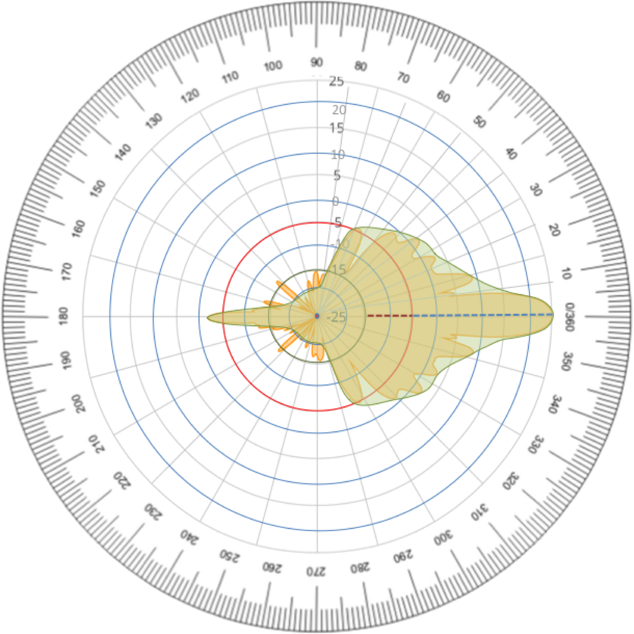
Figure 12 – B5 Antenna Pattern on 360° Compass
When a second antenna pattern is overlaid (Figure 13), we can imagine how the neighboring antenna might amplify an incoming signal intended for the other radio, thus reducing SNR. Note how the dotted blue line is partially obscured in both patterns. Adequate angular separation between the main lobes is necessary to avoid the situation in the image below.
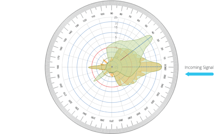
Figure 13 – Two Overlapping B5 Antenna Patterns
By rotating the second antenna away from the first antenna enough such that the main lobe is not obscured, we can start to see what options are available for achieving maximum performance on both links. With two antennas, the second antenna can be anywhere within either of the two green zones which both allow 80 degrees of angular distance (Figure 14).
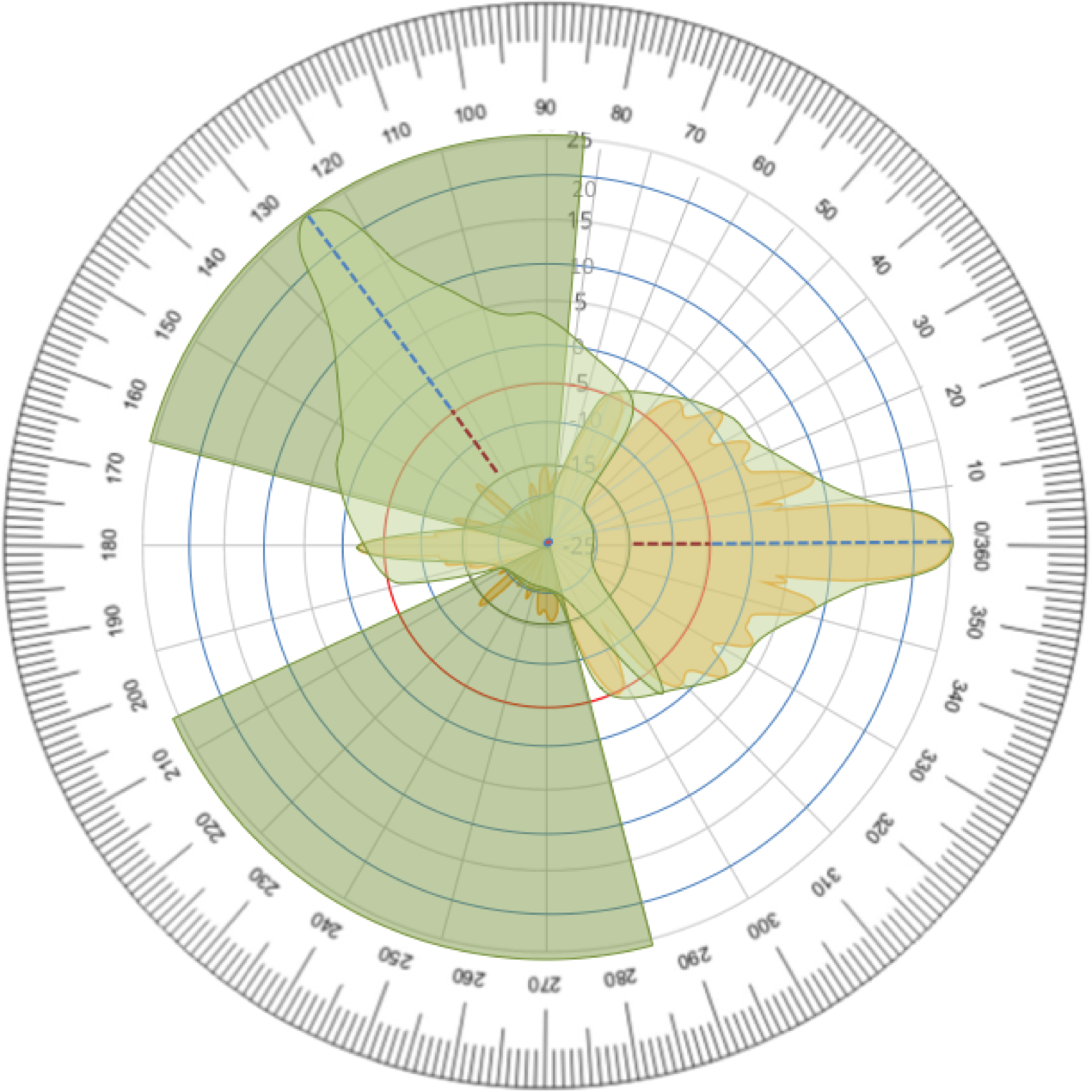
Figure 14 – Two Non-Overlapping B5 Antenna Patterns
If three radios are installed on a tower, the green zones become narrower. It is possible to place the second and third radios within the blue shaded zones without affecting the first radio, but care must be taken to prevent the second and third radios from obscuring each other (Figure 15).
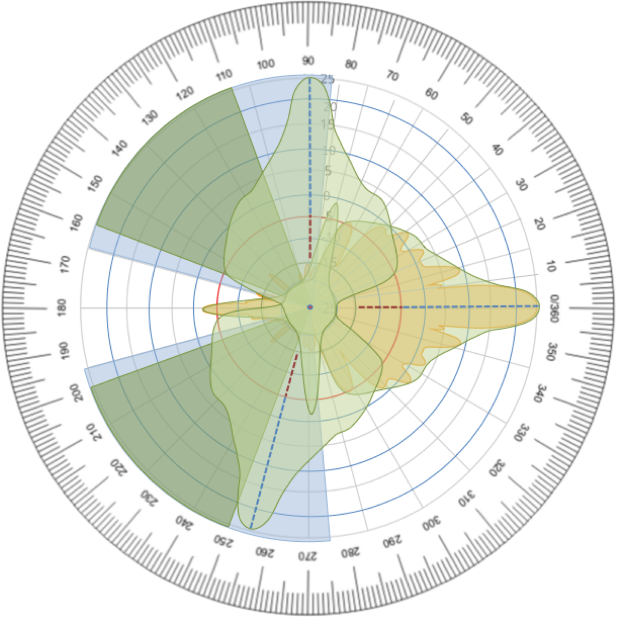
Figure 15 – Three Non-Overlapping B5 Antenna Patterns
Up to four radios using the same channel can be installed per tower following this methodology (at 0, 85, 165, and 245 degrees), while still achieving maximum performance as shown in Figure 16 below.
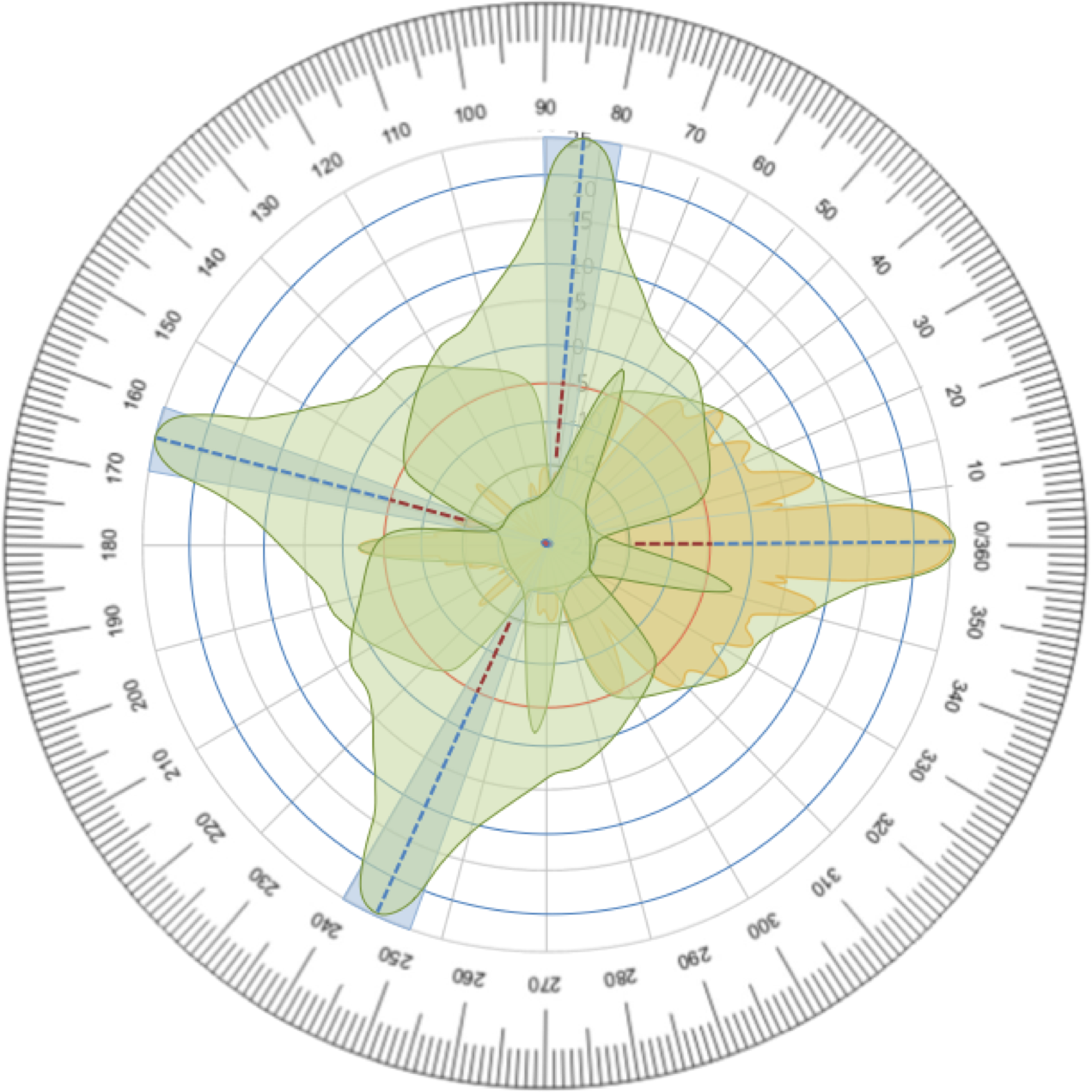
Figure 16 – Four Non-Overlapping B5 Antenna Patterns
In the real world, geography and tower availability often dictate the possible angles. If your design tolerates lower SNR and resulting throughput, additional radios may be added and/or they may be installed at closer angles.
Power Imbalance
Power imbalance between collocated links could also reduce SNR and affect performance. In this case, the objective is to choose a separation angle that results in a small enough gain applied to the incoming “noise” signal such that a desired SNR can still be achieved.
The radio’s ability to receive at a particular MCS index depends on the SNR as shown in Table 2 below. First, choose an MCS index that meets the throughput needs of your customers. For this example we’ll choose 28.5 dB, which represents MCS 9.

Table 2 – SNR Requirements for each MCS Index
Second, calculate the target gain by adding the required SNR from the table above to the Rx signal strength imbalance, and then subtract both from the antenna gain:
Antenna Gain – (Desired SNR + Rx signal strength imbalance) = Target Gain
Example: 25 dBi – (28.50 dB + 10 dBm) = -13.5 dBi
Note: The 25 dBi gain comes from the antenna datasheet. The 10 dBm Rx signal strength imbalance is just an example value.
Third, compare the target gain to the antenna pattern to determine the appropriate angle. Ideally, this is done with antenna pattern data, like in Table 3 below, but it can also be determined manually with a sufficiently detailed pattern diagram. Using the -13.5 dBi gain calculated above, find the next smallest gain value and angle (in this case, 80 degrees).

Table 3 – Antenna Patterns Data (Partial)
The table below summarizes MCS index that two radios can achieve for various angles (0-180 degrees) with Rx signal strength imbalance (0-10 dBm).

Table 4 – MCS Index Achievable with two B5’s by Azimuth and Power Imbalance
Other Radios
Mimosa radios do not synchronize with non-Mimosa radios, although some general rules of thumb apply to avoid interference that non-Mimosa radios may cause.
Ensure at least three meters (ten feet) of physical separation in both vertical and horizontal directions, greater than 30° angular separation, and 20-30 MHz of frequency separation depending on the Power Spectrum Density (PSD) mask of the neighboring radio.
The built-in Spectrum Analyzer in Mimosa’s Backhaul products can be used to select channels with the lowest amount of noise.
Summary
Mimosa chose the TDMA protocol because of its superior efficiency and enhanced resiliency in dual-channel modes. The B5/B5c are equipped with a high accuracy, high precision GPS-DO circuit that enables shared spectrum between collocated radios.
The Mimosa user interface provides options for controlling TDMA parameters for performance tuning.
Angular separation and power imbalance can both affect link performance even with TDMA, so consider these parameters as part of best practice in link design.
Please visit cloud.mimosa.co to access RF planning tools that can aid in this process.